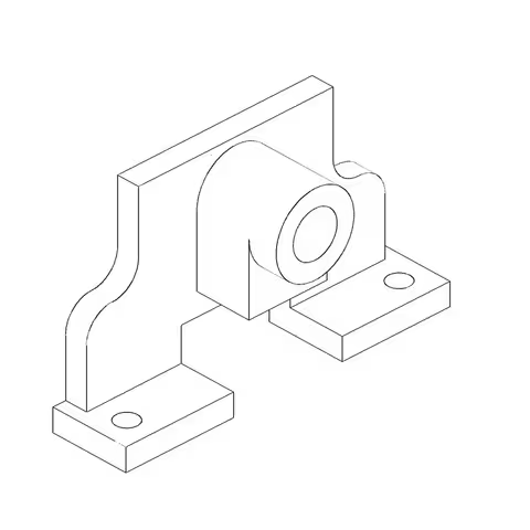
Engineering drawing → executable CAD
IIT Madras · Engineering Design · 7 Oct 2026

Can AI actually read an engineering drawing?

Not “can it make something that looks close?” Can it turn a dimensioned drawing into the right editable CAD model — and know when it is wrong?

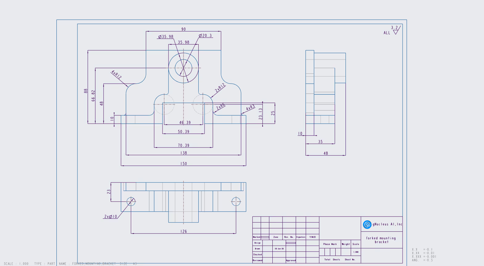
Dimensioned orthographic engineering drawing of a forked mounting bracket

The only geometry source we gave the agent.

The engineering drawing given to Codex

Give Codex only what an engineer would start with.

One drawing. One CAD runtime. One instruction: build the real thing, not a picture of it.

1
The drawingThree orthographic views, dimensions, radii and diameters.
2
FreeCAD 1.1Write Python. Build an editable PartDesign model. Save an FCStd.
3
A render commandTurn the current CAD model into a picture so the agent can inspect its work.
4
A constraintThe drawing is the only geometry source. No hidden reference. No grader.

First, it got stuck looking.

Codex tried to compare the views by making crops and zooming into the drawing. A tooling detour ate the run. It never reached CAD.

Full engineering drawing
More looking. Still no CAD.
Compare viewsFront. Side. Plan.
Make cropsZoom in on details.
Tool detourImage tooling fights back.
No modelTime is gone.
So we changed the workflow, not the model:
stop inspecting forever; start building.
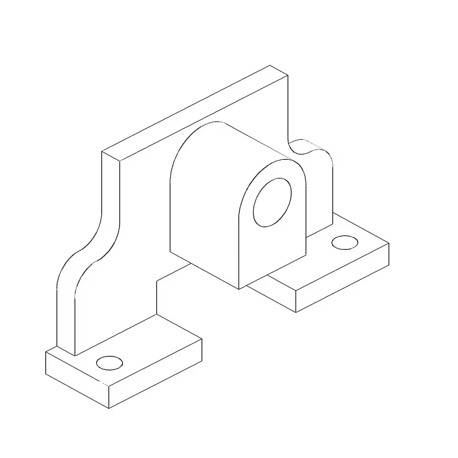
First parametric CAD reconstruction made by Codex

A plausible part appears.

150 × 48 × 88
bounding box, mm
1
valid closed solid
161,285
volume, mm³

It looks like the drawing. Its own coarse checks pass. This is exactly where a demo usually ends.

Then Codex changed its mind.

It noticed that it had treated the eye and support as one 48 mm-deep feature. It rebuilt the support at 35 mm and let only the circular eye reach 48 mm.
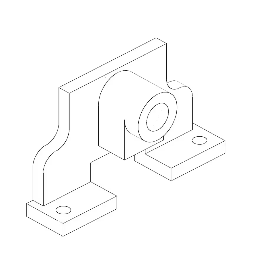
First modelone deep eye/support
First CAD model before self-correction
Revised modelsupport + separate eye
Revised CAD model after self-correction
“The first model is a valid single solid with a 150 × 48 × 88 mm bounding box. I’ll refine the eye…” Codex trajectory, before the second build

This matters: the agent did not just emit one answer. It built, inspected, reconsidered, and repaired.

Nothing it tested said “wrong.”

Exact outer envelope150 × 48 × 88 mm
Valid closed solidFreeCAD Shape.isValid() passes
Editable PartDesign model7 sketches + 7 CAD operations
Plausible renderIt looks like the right kind of bracket
Final Codex CAD reconstruction

Now show it the answer it never saw.

CAD Bench has a held-back reference model. Before comparing anything, we rigidly re-orient it into the Codex frame. Same center. Same scale. Same orientation. Same camera.
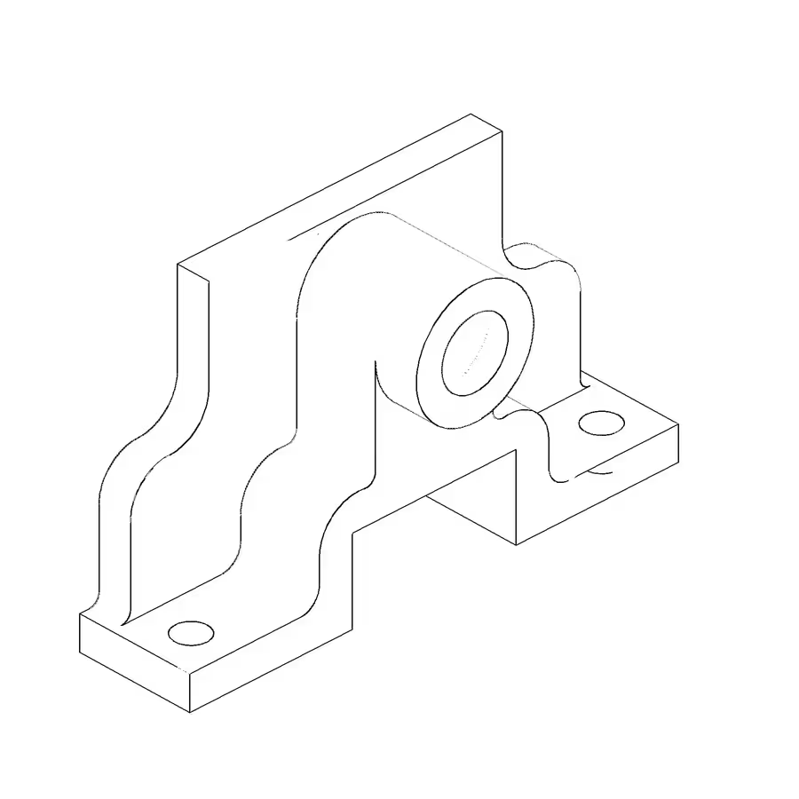
Hidden referenceground truth
Hidden reference CAD model
Codexblind reconstruction
Codex blind CAD reconstruction in the same camera view
Reference Codex
Reference Codex

They are clearly related. But are they the same engineered object?

It does not trust the picture.

The verifier gets three things: the candidate, a hidden reference model, and a hidden specification. Then it checks two different notions of correctness.

Candidate.FCStd

The model the agent built.

Reference.FCStd

Held back from the agent.

Spec.json

30 expected dimensions and structural parameters.

Geometry fidelity

  • solid count
  • oriented bounding box
  • volume and surface area
  • surface types
  • principal moments
  • aligned face-centre residuals
geometry0.042

Spec consistency

  • dimensions and diameters
  • radii
  • counts
  • offsets and references
  • feature-history measurements
spec0.700
harmonic mean
0.0798
overall

It read most of the numbers. It still built the wrong part.

27/30
spec parameters consistent
Most labeled dimensions could be found somewhere in the CAD.
4.2%
geometry similarity
The material distribution and surfaces were substantially different.

The outer bounding box was an exact match. That did not save it. Same size is not the same thing as same geometry.
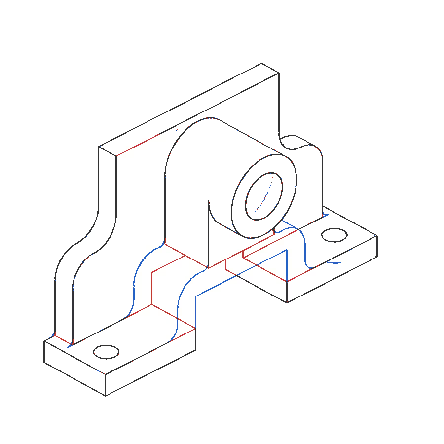
Aligned outline difference: dark where reference and Codex overlap, blue for reference-only geometry, red for Codex-only geometry
overlap reference only Codex only
Bounding box0.0% diff
Volume13.7% diff
Surface types20.2% diff
Principal moments16.8% diff
Face-centre alignment8.44 mm RMSE

One caveat: 27/30 does not mean “90% understood.” The spec checker searches for matching measurements, so a value can occasionally match the wrong feature. That makes the geometry branch even more important.

Codex told itself a different geometric story.

The hidden reference and Codex both use sensible CAD operations. They just compose the part differently.
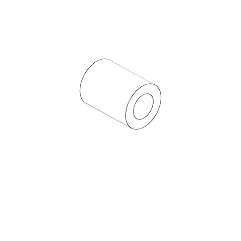
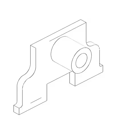
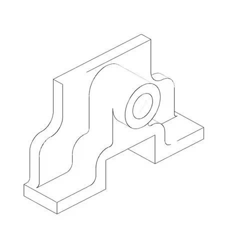
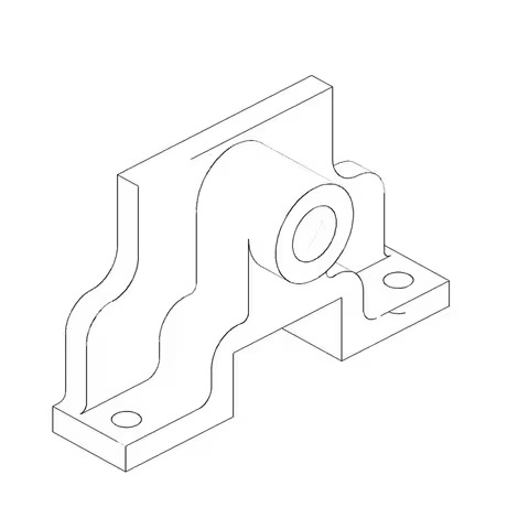
Reference
Reference construction stage 1
Eye / boss profile
Reference construction stage 2
Add main body profile
Reference construction stage 3
Add lower / fork profile
Reference construction stage 4
Cut mounting holes
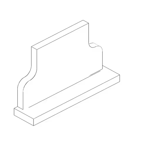
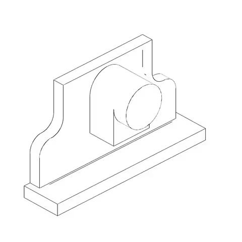
Codex
Codex construction stage 1
Base + upright
Codex construction stage 2
Add separate circular eye
Codex construction stage 3
Cut rectangular fork + bore
Codex construction stage 4
Cut mounting holes
R3Expected a 3 mm lower-profile radius. Nearest candidate radius was R5.
R6Expected an R6 feature. No final-geometry witness existed.
46.39 mmExpected a fork reference. Nearest candidate measurement was 48 mm.

The failure was not “it cannot read numbers.” It was: the numbers were attached to the wrong geometric relationships.

The agent improved against the tests it had.

Its checks were useful. They were just too weak to establish engineering fidelity.

What it checked

  • bounding box
  • one valid closed solid
  • editable feature tree
  • plausible rendered appearance

What it did not check

  • R3 / R6 final profile geometry
  • material distribution and volume
  • surface types and topology
  • whether each dimension belonged to the right relationship

Self-verification is only as strong as the verification kit.

Put CAD-Bench-like checks inside the agent loop.

Do not wait until the end to discover that the model is beautifully valid and geometrically wrong. Give the agent engineering-grade ways to fail early.

Drawread the source
→
Modelbuild editable CAD
→
Testmeasure independently
Repairtarget the failed invariant
←
Diagnosewhich relationship is wrong?
←
Fail loudlybefore calling it done
Valid solid + editable feature structure
Dimensions, radii, holes and counts
Check values on the right features
Bounding box, volume, surface area
Mass / principal moments
Surface types and topology
Geometric alignment and residuals
Assembly / clearance / physics when relevant

If we want an agent to behave like an engineer, we have to give it engineering-grade ways to know when it is wrong.

Discuss

What does it mean to understand an engineering drawing?

Reading the numbers is not enough. Making a recognizable shape is not enough. So where should we draw the line?

Read the callouts? Recover exact geometry? Recover design intent? Pass assembly tests? Pass physics tests? Know when to ask?